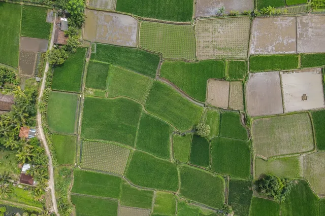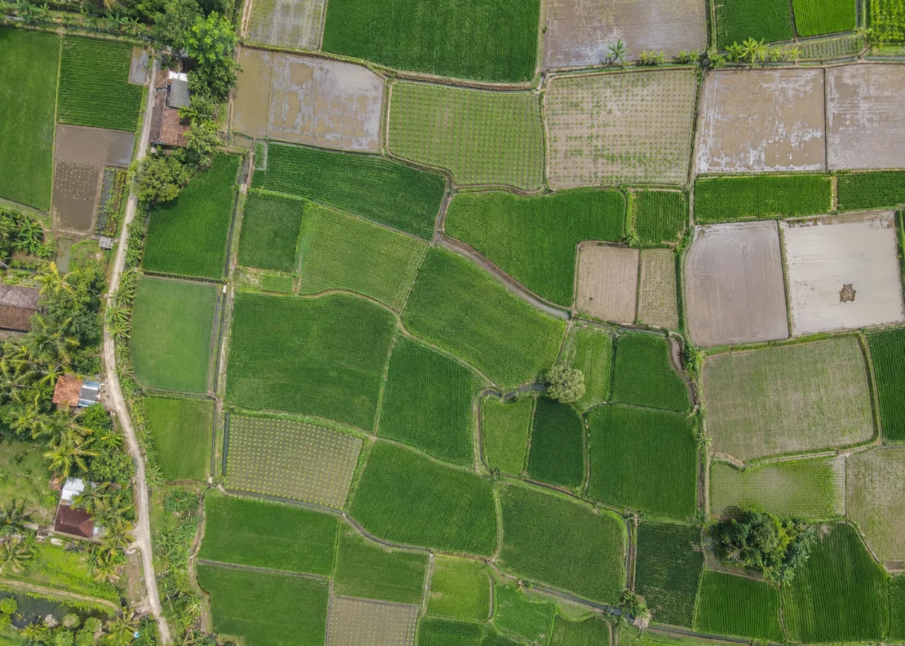
Start with the operational question
Irrigation problems can appear as localized wet ground, unusual canopy patterns or repeated strips aligned with delivery infrastructure. Mapping the infrastructure and the crop together helps distinguish isolated anomalies from broader soil or terrain patterns. The objective is a prioritized inspection route, with equipment measurements determining the actual fault.
The working question is: Which spatial patterns suggest an irrigation leak, blockage or delivery inconsistency to investigate? Define irrigation inspection zones before the survey begins and identify who will review them. Agree what evidence would change an inspection, sampling or management decision. This keeps the map tied to a testable task and makes it possible to distinguish a useful observation from an attractive output that cannot resolve the question.
Understand what the image actually observes
Rainfall, shade, soil texture and crop stage can produce similar patterns. Thermal contrast changes with weather and time, and a cool patch may be open water rather than a well-supplied crop. A single image cannot identify the hydraulic cause.
For irrigation inspection zones, the measurement definition is part of the result. Separate the planted area from roads, bunds, headlands, permanent vegetation and water where these are outside the assessment definition. Decide whether the measurement unit is a plant, row length, patch or management block, and keep that unit consistent through analysis and reporting. Soil background, crop age and canopy overlap affect what is observable. Maintain an unknown or obscured class instead of forcing every location into good or poor condition. A transparent denominator and valid-observation fraction make the resulting agricultural comparison much easier to interpret than a single whole-farm percentage.
Design capture around the target and its confounders
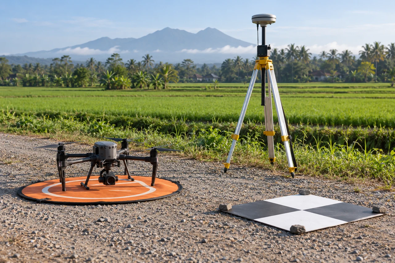
Capture planning for irrigation inspection zones should begin with the intended comparison. Choose an observation window that matches crop stage and the field question. Record planting dates, recent irrigation, rainfall and management events. Inspect sample photographs for blur and confirm that the smallest relevant crop feature is visible before committing the entire field to processing. Keep repeated observations as comparable as practical in illumination and camera configuration, while recording unavoidable differences. Where reflectance-based indices are required, use suitable spectral bands and an evaluated radiometric workflow; an ordinary RGB color adjustment is not equivalent to measuring near-infrared reflectance. Include representative intact crop as well as the suspected anomaly in the planned coverage.
Build a traceable processing and analysis workflow
Join verified irrigation-line or pivot geometry to current imagery and recent operating records. Mark anomaly shapes and their relation to emitters, laterals and pressure zones. Compare observations taken under comparable operating conditions. Check whether patterns recur before recommending infrastructure changes.
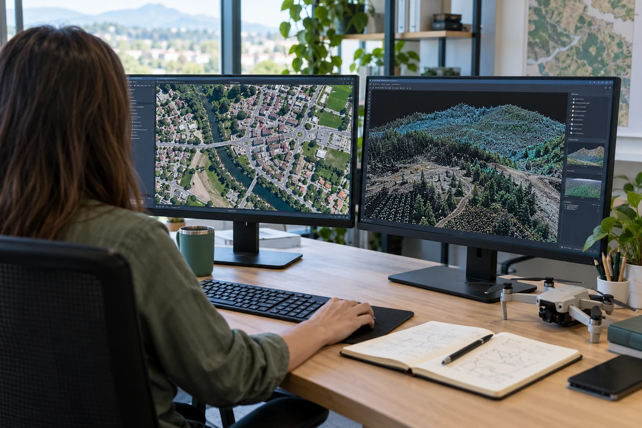
Quality review for irrigation inspection zones must continue after processing completes. Review a low-resolution alignment before relying on full outputs, then inspect the finished mosaic against original frames at anomaly edges. Reject blur, severe seams and unsupported areas rather than smoothing them into an apparently complete crop map. If an index is used, verify band identity, alignment and invalid values. If structure is used, inspect the point cloud and surface support instead of assuming every raster cell is measured. Summarize distributions and valid area within the intended crop units, preserving the field identifiers needed by agronomists and operations staff.
Work through an illustrative example
Suppose an illustrative lateral has a persistent wet patch near one connection while neighboring rows remain dry. A ground inspection finds a loose fitting. Elsewhere, a similarly wet patch follows a natural depression with no leak. Shape and context made both worth inspecting, but only measurement established the difference.
This example for irrigation inspection zones is deliberately illustrative, not a reported outcome or an accuracy promise. Replace its assumptions with the project’s measured values before using the reasoning operationally. Keep the numerator, denominator, observation date and exclusions visible. If a plausible boundary, visibility or reference change alters the decision, collect the missing evidence or retain the case as unresolved rather than reporting extra decimal places.
Validate with independent field evidence
Measure flow or pressure where appropriate, inspect fittings and note recent irrigation timing. Compare soil moisture and plant condition in flagged and reference zones. Coordinate the visit so the system state is known during both image capture and field checking.
An evaluation of irrigation inspection zones should include both flagged targets and suitable unflagged reference locations. Checking only the most obvious candidates can estimate neither the missed targets nor the full false-alarm pattern. Separate observations used to adjust the method from those used to evaluate it. Keep the sampling unit and selection method explicit, and report difficult or unobservable cases rather than dropping them silently. When field timing differs from image timing, explain whether the site could have changed between visits. A disagreement is evidence to investigate, not an instruction to force the ground record to match the map.
Resolve the topic-specific interpretation risks
Irrigation inspection records should connect the anomaly to the equipment state at the time, including whether the relevant line was operating. A suspected leak observed while the system is off may instead reflect residual water or another source. After a confirmed repair, retain the original fault location and create a new verification record. This supports a useful maintenance history and avoids erasing evidence when the current map looks normal. If a crop anomaly persists after the hydraulic fault is corrected, continue the agronomic investigation rather than assuming the repair disproved the image observation.
Hand over evidence that the receiving team can use
Deliver an issue register distinguishing suspected delivery faults from unexplained crop patterns. Verify repairs through operational checks and a comparable follow-up observation rather than assuming color normalization proves the fault is resolved.
For the irrigation inspection zones handover, retain stable identifiers, the source observation date, the coordinate reference, the analysis boundary and the valid-observation status. Supply both an accessible overview and the relevant geospatial data where needed. Attach a short exception register that explains unresolved features and the next useful check. If the data are revised, preserve the reason and version so quantities or statuses can be traced. Ask the receiving team to locate a sample item and interpret its confidence; that practical review often reveals missing context that a file-integrity check cannot detect.
When evaluating Drone Mapping Software for irrigation inspection zones, assess the complete workflow with a representative dataset. DroneCollab can be considered for preparing photogrammetric mapping outputs, while task-specific interpretation and field validation remain essential. Compare the required exports, review process and actual pilot evidence before selecting a workflow for recurring work.