What the measurement actually means
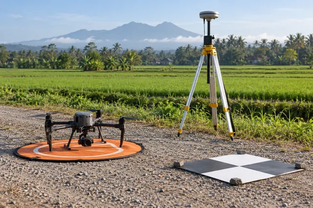
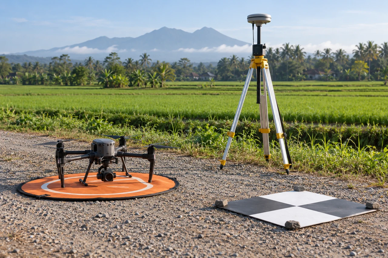
Multipath occurs when a receiver observes reflected signals in addition to, or instead of, the direct path. Reflectors can include building facades, vehicles, equipment, and water surfaces. The effect depends on geometry, antenna characteristics, signal processing, and changing motion, so it is often site specific. A nearby reference receiver does not automatically cancel rover multipath because the two antennas see different local reflections. Smooth coordinates and a favorable satellite count can therefore coexist with a locally biased navigation solution.
A reproducible working procedure
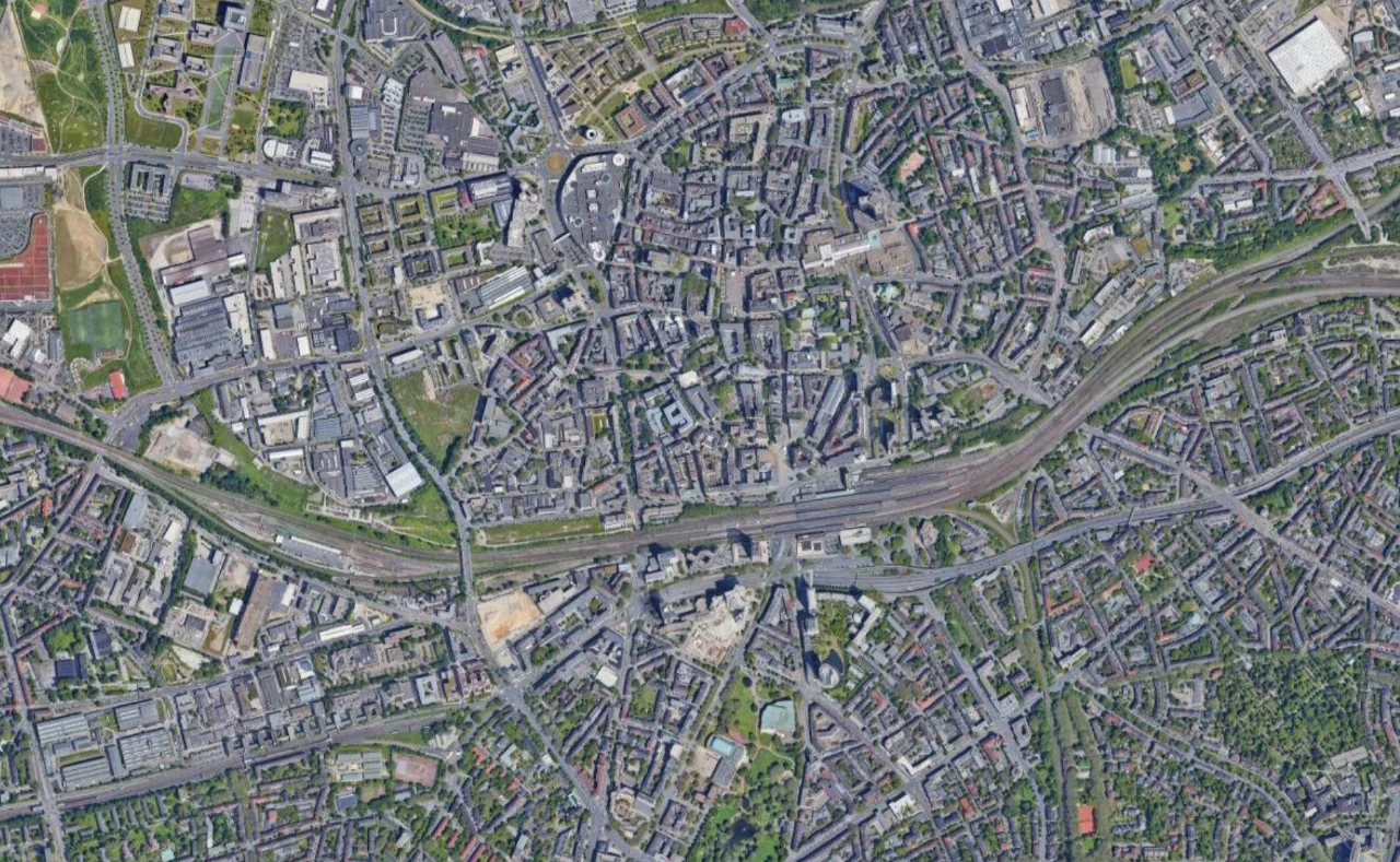
Document the antenna surroundings and inspect whether large reflective objects or obstructions change during the session. Compare signal quality and observation residuals by satellite, elevation, and time. For a base station, choose a stable location with open sky and follow the antenna installation guidance. For a moving rover, identify image intervals near problematic structures and compare them with less obstructed segments. Retain raw observations so alternative screening can be assessed without replacing evidence with a manually smoothed coordinate track.
Illustrative calculation and interpretation
Imagine an illustrative reflected code path that is eight metres longer than the direct path. The observed range bias is not necessarily eight metres because direct and reflected signals combine through receiver tracking behavior. If that affected observation is accepted, its coordinate effect also depends on satellite geometry and weighting. A separate illustrative repeat pass might show a 0.4 metre local coordinate discrepancy near a wall but much smaller discrepancies in open sky. That pattern supports targeted investigation without proving multipath as the only possible cause.
Quality checks and failure diagnosis
Inspect repeatability at different times, but recognize that changed satellite geometry can change the reflection pattern. Do not estimate a universal correction by subtracting one observed local discrepancy from every pass. Check antenna placement, cable integrity, and reference coordinates as separate possibilities. Use independent ground features and navigation diagnostics together to assess affected images. Flag unresolved reflective environments in the project record, especially where the intended measurement depends on small relative movements that could be confused with location dependent navigation bias.
Build an evidence chain
Keep the original receiver observations, camera event records, sensor configuration, and processing log together before editing anything. Work on copies and record file checksums so that a later discrepancy can be traced to a particular input. A useful evidence table links each image name to its event time, trajectory record, solution status, and exclusion reason. Missing entries deserve investigation before a reconstruction starts; an attractive map cannot restore observations that were never recorded or establish which clock supplied an undocumented timestamp.
Separate precision from reference accuracy
A tightly clustered navigation solution describes repeatability under the assumptions used by its estimator. It does not prove that the base coordinate, height system, sensor origin, or camera exposure time is correct. Treat those items as separate parts of the measurement chain. First inspect internal consistency, then compare against independent surveyed features that were withheld from any adjustment. Report a directional bias as well as scatter, because an almost constant displacement can coexist with a very small estimated position standard deviation.
Design a controlled comparison
Change one processing choice at a time and retain both outputs. Compare a common time interval and the same image subset, rather than allowing different exclusions to disguise the effect. Plot the coordinate differences against time, speed, turning rate, and solution status. A step, a smooth drift, and a periodic oscillation suggest different mechanisms. Write down the expected signature before looking at the result; this reduces the temptation to explain every pattern after the fact or to choose settings merely because their report looks better.
Make uncertainty operational
Create an uncertainty register with columns for source, units, possible bias, temporal behavior, and the evidence used to estimate it. Combine independent random components through variance only when independence is defensible. Keep shared reference errors and unknown systematic effects visible instead of dividing them by the number of photographs. Translate the resulting uncertainty into the actual task: locating an asset, comparing elevations, or estimating a boundary displacement may require different acceptance decisions even when they use the same underlying image collection.
Check independent locations
Distribute independent checks through the mapped footprint and across relevant surface types. Record how each reference point was measured, how its center was identified in the output, and whether the surrounding terrain permits a stable comparison. Inspect residual arrows and height differences spatially, then summarize the valid sample with its count and coverage. Do not silently delete difficult checks. Investigate them, document exclusions, and distinguish a demonstrated acquisition problem from a reference measurement or interpretation problem before accepting the deliverable.
Preserve the release context
The handover should state the observation date, coordinate reference frame, vertical convention, time scale, sensor offsets, processing version, and checks actually performed. Include any interval that relies on a degraded navigation solution and explain how those images were handled. Preserve a machine readable manifest beside a short human readable note. A reviewer should be able to reproduce the selection of usable observations and understand the limits without access to the original operator or a screenshot of a temporary application dashboard.
Test the decision, not just the file
Define the downstream decision before choosing an acceptance tolerance. An overview map, a repeat survey comparison, and an engineering measurement can use similar looking files while requiring different evidence. Write the tolerance in physical units and state the footprint where it applies. If the available checks do not cover a surface type or operating condition, identify that gap explicitly. This makes a conditional acceptance useful: the analyst can release a supported portion, retain a flagged portion for investigation, and avoid silently extending evidence beyond the locations actually examined.
Distinguish an assumption from an observation
Keep a short interpretation note separating measured quantities, calculations, and assumptions. The numerical example in this article is an illustration of a mechanism; replace its inputs with project measurements before making an operational decision. For an uncertain input, repeat the calculation over a defensible range and see whether the conclusion changes. If it does, obtaining better evidence for that input may be more valuable than adjusting unrelated processing settings. Retain the alternative results so a reviewer can understand why the selected workflow was judged adequate.
Using the result in a mapping project
Drone Mapping Software is most useful here when its outputs remain connected to the documented inputs and checks. A DroneCollab project can be considered as one processing destination, while the analyst retains responsibility for coordinate interpretation, independent validation, and suitability for the intended measurement. Confirm the available import and export options for the actual project rather than assuming that a product name establishes support or accuracy.