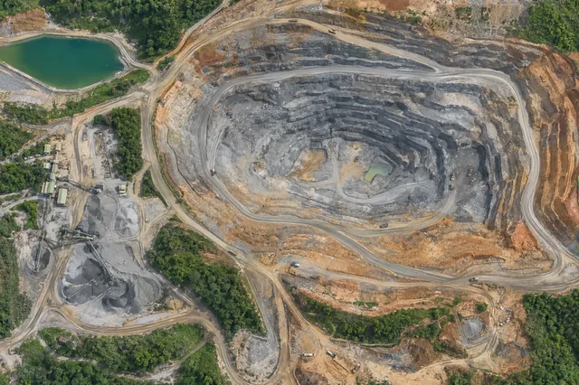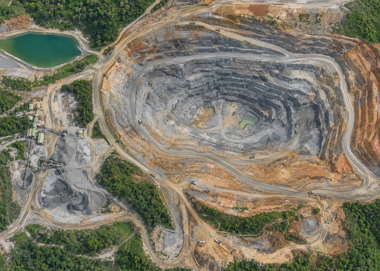
Start with the operational question
Quarry mapping can document bench edges, exposed faces, access and visible surface geometry. Steep faces require suitable viewing angles because a nadir-only survey may not see them adequately. The model should identify the actual observed surface and provide useful sections without suggesting that geometry alone establishes geotechnical condition.
The working question is: Which bench geometry can be measured reliably from the visible reconstructed surface? Define quarry bench sections before the survey begins and identify who will review them. Agree what evidence would change an inspection, sampling or management decision. This keeps the map tied to a testable task and makes it possible to distinguish a useful observation from an attractive output that cannot resolve the question.
Understand what the image actually observes
Occluded faces, repetitive rock texture and interpolation across gaps can create convincing but unsupported surfaces. A clean mesh may bridge an overhang or missing face. Surface detail also does not reveal internal fractures or material properties.
For quarry bench sections, the measurement definition is part of the result. Separate the observed surface from a hidden base, an engineered design and any inferred subsurface feature. State the inventory or analysis boundary and the timestamp or capture interval. Decide whether the quantity is area, geometric volume, profile position or a neutral feature observation. Mass needs additional density evidence, and water storage needs suitable level and basin information. Keep temporary objects and unsupported faces out of consequential surface calculations unless the method explicitly handles them. A detailed model cannot remove uncertainty in the definition of the quantity being estimated.
Design capture around the target and its confounders
Capture planning for quarry bench sections should begin with the intended comparison. Coordinate the survey window and viewing geometry with responsible site staff. Record active earthmoving, material handling, water operations and temporary obstructions that may change the surface during capture. Steep faces and complex piles need suitable coverage rather than an assumption that a top-down grid sees everything. Use stable reference locations and independent checks appropriate to the intended measurement. Site access and field observations should follow established operational procedures. The aerial survey contributes dated visible geometry; engineering condition, subsurface state and operational safety require the responsible professionals’ wider monitoring and inspection evidence.
Build a traceable processing and analysis workflow
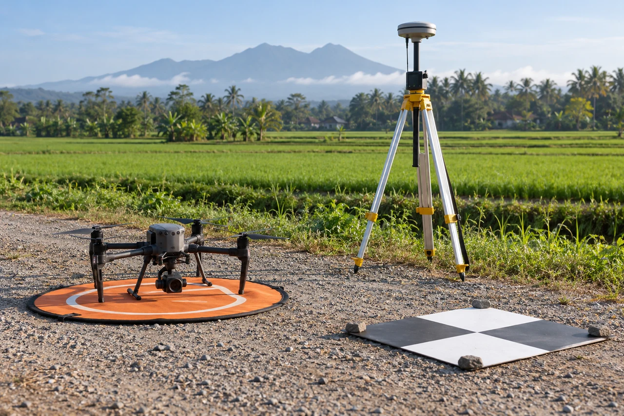
Define the required bench sections with site survey staff, plan adequate face observations and retain control on stable accessible ground. Inspect image coverage and point support at edges. Generate sections from qualified data and flag interpolated or hidden areas. Keep design geometry separate from the observed survey.
Quality review for quarry bench sections must continue after processing completes. Review geometry at steep faces, pile edges, water margins and repetitive surfaces, using original images and point support. Mask occlusion and interpolation that cannot support the measurement. Confirm coordinate and vertical references before comparing with design or earlier surveys. Retain the chosen boundaries, base surfaces and processing version with the result. Test the sensitivity of quantities to reasonable alternatives where hidden or ambiguous geometry matters. Distinguish known operational change from unexplained differences, and have consequential findings reviewed through the site’s responsible survey, engineering or inspection process.
Work through an illustrative example
Suppose an illustrative section appears to show a continuous face, but the point cloud has a wide unsupported gap. The interpolated profile cannot confirm bench width through that gap. A changed viewing geometry or another measurement method is needed before using the section for a consequential decision.
This example for quarry bench sections is deliberately illustrative, not a reported outcome or an accuracy promise. Replace its assumptions with the project’s measured values before using the reasoning operationally. Keep the numerator, denominator, observation date and exclusions visible. If a plausible boundary, visibility or reference change alters the decision, collect the missing evidence or retain the case as unresolved rather than reporting extra decimal places.
Validate with independent field evidence
Check accessible surveyed points and selected sections using an appropriate independent method. Review observed geometry with the responsible site professionals. Keep inspection personnel out of hazardous areas and follow the site’s established controls.
An evaluation of quarry bench sections should include both flagged targets and suitable unflagged reference locations. Checking only the most obvious candidates can estimate neither the missed targets nor the full false-alarm pattern. Separate observations used to adjust the method from those used to evaluate it. Keep the sampling unit and selection method explicit, and report difficult or unobservable cases rather than dropping them silently. When field timing differs from image timing, explain whether the site could have changed between visits. A disagreement is evidence to investigate, not an instruction to force the ground record to match the map.
Resolve the topic-specific interpretation risks
Bench sections should carry a measured-support indicator along the profile so users can distinguish point-supported portions from interpolated gaps. Review breaklines and overhangs in three dimensions, because a raster surface allows only one height at each horizontal location. If that representation cannot express the face geometry, choose a more appropriate output for the review. Keep the design and survey versions visible in the section labels. A discrepancy can then be traced to actual geometry, unsupported observation or an outdated design reference rather than being treated as one undifferentiated error.
Hand over evidence that the receiving team can use
Deliver qualified bench sections, coverage flags and dates. Geotechnical assessment and operational acceptance require the responsible professionals’ broader evidence, beyond a visually detailed three-dimensional model.
For the quarry bench sections handover, retain stable identifiers, the source observation date, the coordinate reference, the analysis boundary and the valid-observation status. Supply both an accessible overview and the relevant geospatial data where needed. Attach a short exception register that explains unresolved features and the next useful check. If the data are revised, preserve the reason and version so quantities or statuses can be traced. Ask the receiving team to locate a sample item and interpret its confidence; that practical review often reveals missing context that a file-integrity check cannot detect.
When evaluating Cloud Photogrammetry Software for quarry bench sections, assess the complete workflow with a representative dataset. DroneCollab can be considered for preparing photogrammetric mapping outputs, while task-specific interpretation and field validation remain essential. Compare the required exports, review process and actual pilot evidence before selecting a workflow for recurring work.